Creating a Lithology Model from a Master Log Lithology File
Apart from creating a lithology model based on a zonation model or based on an input lithology log, you can also create a lithology model from a master lithology log file. With the Master Log Lithology tool, you use an image, the master log lithology file, to create a custom made lithology model. This lithology model will then be used in all subsequent calculations. If you already had a lithology model assigned to your 1D case, you are prompted with a warning that it will be overwritten.
The tool has three sections:
- An input section at the top where you select an image and define the top and base MD of the lithology model.
- A viewer section where the selected image is displayed and you do your manual interpretation.
- A schematic section where the interpreted segments are displayed and you assign a rock type.
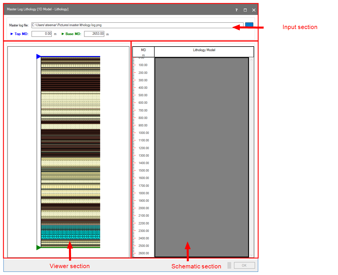
The Master Log Lithology form click to enlarge
Creating custom lithology model
- To open the tool, go to 1D Model > Lithology > Master Log Lithology.
- Upon opening, the top MD and Base MD entry fields are populated with the top MD and base MD of the wellbore that is associated with the active 1D Case. These values will be used for the top and base MD of the image and the schematic section. To edit these values, double click inside the entry field and enter a new value to use as top or base MD.
- Click the Edit button
 to open a file explorer where you can select the master log (image) file. Select the file of interest and click Open to import the file and display it in the viewer section.
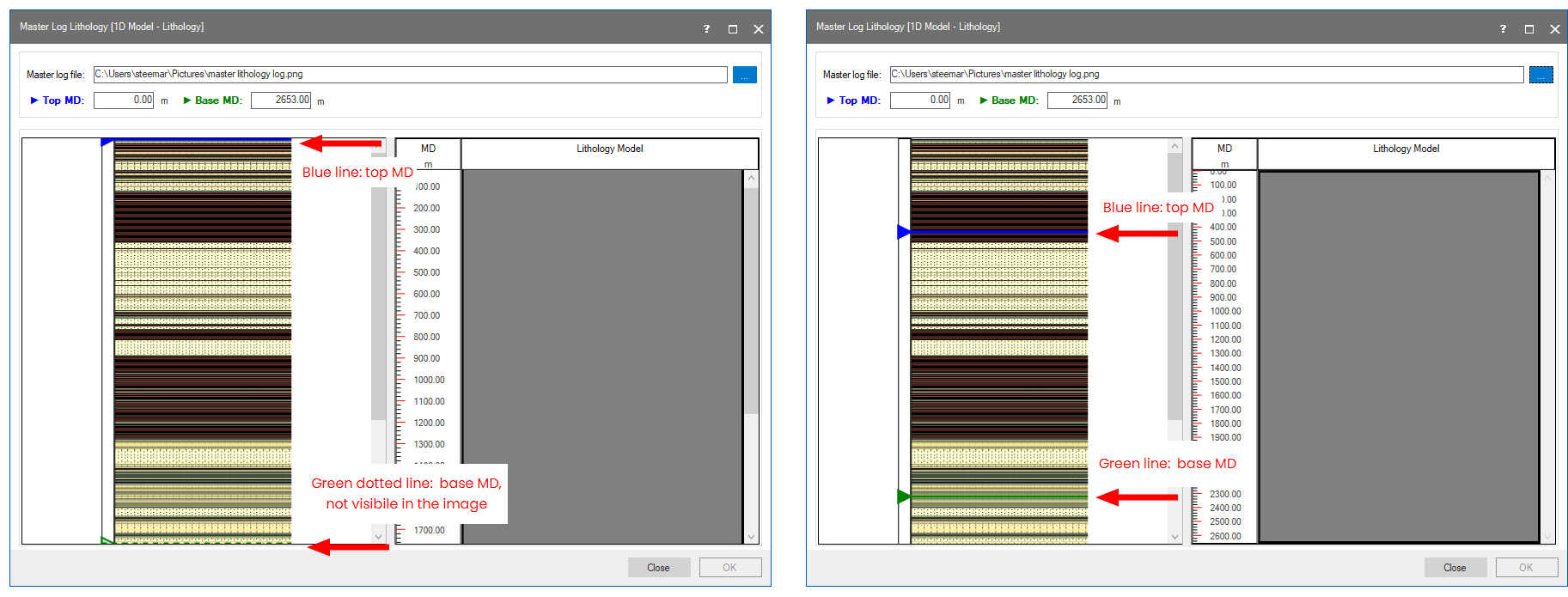
 - In the viewer section, a blue and green line appear to indicate the top and base MD used for the image, as indicated in the entry fields in the input section. By default they are located at the top and bottom of the image. Left mouse click and drag to move the sliders to a different position if needed. This new position is then considered the top MD (blue slider) or base MD (green slider), with the values listed in the entry fields in the input section. If the blue or green line is dotted, it means it is not shown at the top or the base of the image. In this case, use the slider on the side to move the image up and down, or enlarge the form.
- In the viewer section, left mouse click and drag to select a segment of the image. The start and stop MD of this segment are listed and the segment is highlighted in purple.
- Double click to create the highlighted segment in the schematic representation.
- Right click on the segment in the schematic section to open the context menu and assign a rock type from the drop-down list.
- Repeat steps 5,6 and 7 to create a custom lithology model.
- The two sections are interactive, if you click on a segment in the schematic section, it will highlight the same segment in the viewer section. If needed you can adjust the start and end MD of a segment in the viewer section. Hover over the start or end MD and wait until the mouse pointer changes into a bidirectional arrow. You can now move the line. Double click to update the segment in the schematic section.
- Click OK to create the custom lithology model and close the form. If the active case already has a lithology model assigned to it, you will be prompted with a warning to overwrite it. Any view that already displayed the lithology model is updated immediately.
Move the slider to set a new top and base MD to use in the image. Note that the scale in the schematic section is updated accordingly. click to enlarge
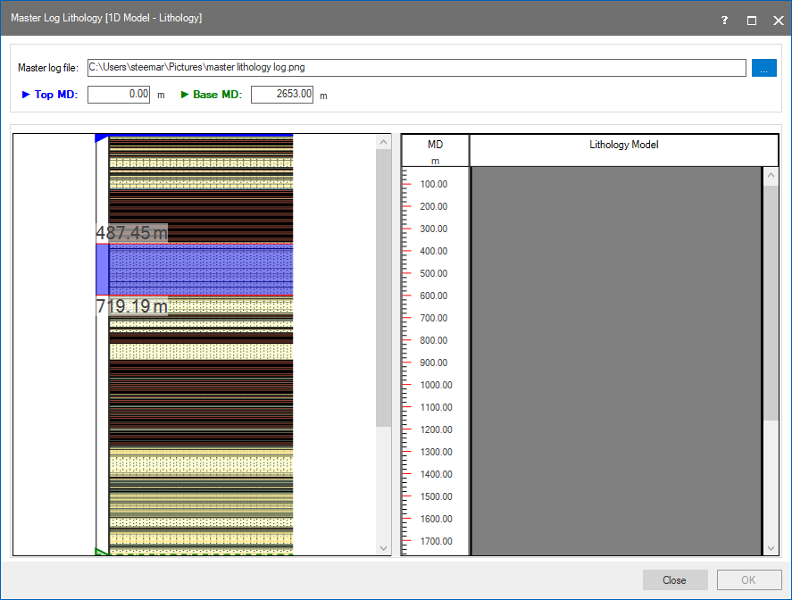
Select a segment in the viewer section. The segment is highlighted and the start and end MD are listed. click to enlarge
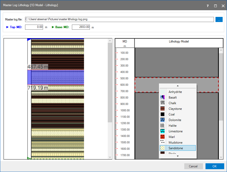
Use the context menu to assign a rock type to the segment. click to enlarge
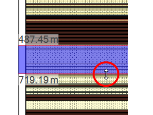
Move the start or stop MD of a segment, the mouse pointer changes into a bidirectional arrow when you hover over. click to enlarge